When the machine starts, you can enter BASIC commands.
PRINT "HELLO WORLD"
This will print “HELLO WORLD” to the screen. You can also make a BASIC program. Enter these commands, including the number in front:
10 PRINT "HELLO"
20 PRINT "WORLD"
This is a small BASIC program that will print HELLO on the first line and WORLD on the second line.
Ececute the program with RUN. You can examine the BASIC program with LIST.
Programs can be saved and restored to/from disk, using SAVE "FILENAME.PRG" and LOAD "FILENAME.PRG"
The first 2 bytes of the PRG file contains the destination address in RAM, stored as little endian. The rest of the PRG file contains the payload. The destination address is usually 0x0801, which is where the BASIC program is supposed to be stored in RAM.
Each line of BASIC contains 16 bit address to next line, 16 bit line number, 8 bit BASIC token, zero-terminated string with rest of line.
RAM can be examined using monitor MON:
M 0801
.:0801 0F 08 0A 00 99 20 22 48
Here is a full dump of the simple BASIC program above:
10 PRINT "HELLO"
.:0801 0F 08 (address to next line, 0x080F)
.:0803 0A 00 (line number 0x000A -> 10)
.:0805 99 (BASIC token for PRINT)
.:0806 20 22 48 45 4C 4C 4F 22 00 (The string ' "HELLO"')

20 PRINT "WORLD"
.:080F 1D 08 (address to next line, 0x081D)
.:0811 14 00 (line number 0x0014 -> 20)
.:0813 99 (BASIC token for PRINT)
.:0814 20 22 57 4F 52 4C 44 22 00 (The string ' "WORLD"')

.:081D 00 00 (address to next line, 0x0000. This means end of program)
BASIC programs are not limited to printing. You can make advanced programs using BASIC. However, as this is an interpreted language, it is slower than machine code programs. Thus, most games, and other software which requres higher performance, is represented as machine code instead of BASIC.
Machine code programs
If you want to speed up your application, you can make a machine code application instead. Commander X16 is equipped with a 65C02 microprocessor, which is quite fun to program. This CPU have 3 general-purpose registers: accumulator A, and index registers X and Y. The CPU is a RISC (Reduced Instruction Set Computer), so that it is possible to learn the reduced number of instructions when writing assembly code.
For an excellent 6502 tutorial, I can highly recommend ChibiAkumas website https://www.assemblytutorial.com/6502/ , in particular his printable cheatsheet with assembler mnemonics (instructions).
For this tutorial, I will use the ACME cross-assembler, as that is the assembler suggested by someone in the X16 community (I cannot remember the reference).
The first example will print the character ‘A’ to screen using the KERNAL function CHROUT (for reference, see KERNAL chapter in X16 documentation).
hello.asm
1
2
3
4
5
6
7
8
9
10
11
12
13
14
15
16
17
18
19
; Hello world
;
; Minimalistic assembly program for x16, using acme assembler
; Will print a single "A" to screen using KERNAL

; Machine code program will be loaded at address 0x0810 / 2064
; Execute the machine code program with the BASIC command
; SYS 2064

*=$0810

    lda #'A'  ; Load 'A' (0x41) to register A

    jsr $FFD2 ; Call the KERNAL function at address FFD2.
              ; This is the CHROUT function, which will print
              ; the character in register A to screen.

    rts       ; Return to BASIC
Build this program with acme -v3 -f cbm --cpu 65c02 --report report.txt -o hello.prg hello.asm
To load this program, use the syntax LOAD "HELLO.PRG",8,1. This will load from device 8 (disk/SD-card). The “,1” specifies that the file will be loaded to the absolute address specified by the two first bytes in the file. You can also load the file while starting the emulator using x16emu -prg hello.prg.
To run this program, run SYS 2064. This will execute the machine code routine stored at address 2064 / 0x0810.
It is inconvenient for end users to start programs using this command. To simplify this process, a small BASIC header can be added in front of the machine code program.
; Kernal functions CHROUT=$FFD2 ; Kernal: CHROUT outputs a character to screen
lda #'A' ; Load 'A' (0x41) to register A
jsr CHROUT ; Call the KERNAL function CHROUT. ; This will print the character in register A to screen.
rts ; Return to BASIC
This improved example contains a “BASIC header”. When loading this program, you can view the BASIC program using LIST. The program contains one line, 10 SYS 2064. This means that you can run the machine code program simply by using RUN. This example also shows how you can define a symbol, CHROUT, to make the code easier to read.
I enjoy assembly language programming. Enough that I want to try to write a few blog posts explaining some stuff you can do using this language.
As a quick introduction to assembly language, I want to start with the “Blink” example used by Arduino Uno.
1
2
3
4
5
6
7
8
9
10
11
12
13
14
15
// Examples/Basics/Blink
// the setup function runs once when you press reset or power the board voidsetup(){ // initialize digital pin LED_BUILTIN as an output. pinMode(LED_BUILTIN, OUTPUT); }
// the loop function runs over and over again forever voidloop(){ digitalWrite(LED_BUILTIN, HIGH); // turn the LED on (HIGH is the voltage level) delay(1000); // wait for a second digitalWrite(LED_BUILTIN, LOW); // turn the LED off by making the voltage LOW delay(1000); // wait for a second }
The objective for this application is to toggle the onboard LED of the Arduino. This requires 3 steps:
Set the GPIO pin to output mode
Toggle the output continuously
Add some delay between each toggle, to make the blink visible
Three fairly simple tasks. Each of these requirements are done using only one or two lines of C++ code to achieve.
Building this program, and uploading it to your Arduino Uno, will indeed cause the LED to start blinking. Which is a great starting point for testing and programming your new Arduino Uno.
However, it also reveals that the size of the executable is 924 bytes.
Arduino Uno uses an AVR based microcontroller, ATMega328P, which have 32 kB internal flash for the application. 924 bytes is only 2.8% of the total flash. However, if you are into low-level programming, and know your architecture, you will immediately realize that there are lots of overhead causing this simple task to take 924 bytes. What are these bytes actually used for?
To see what these 924 bytes actually contain, you can open the compiled output and examine it. In the case of Arduino, it is a little challenging to examine the actual output. First, you should enable verbose output using File - Preferences - Show verbose output. Examining this output reveals that the Arduino was programmed using a “hex file”.
Building using Arduino places the build output to a temporary folder. To examine the files, you have to look for this line in the output, and open the relevant folder.
The .hex file contains the program in machine code. You can open this program in a text editor, and it will show the code using the Intel Hex format (16 bytes pr line).
Using a hex editor, you can also examine the raw binary data. Then, you need to execute the command
avr-objcopy -O binary Blink.ino.elf Blink.ino.bin
in the temporary folder. Then you can open the .bin file in any hex editor.
Reading machine code is not very easy to do for human programmers. This is why Assembly language was invented, as a human readable counterpart to machine code. Running the command
avr-objdump -S Blink.ino.elf > Blink.ino.lst
will disassemble the object file. This will print the output to a .lst file, which can be opened in a text editor.
000-067: (104 bytes) Interrupt vectors for 26 vectors a 4 bytes. Each containing a 3 byte JMP instruction
068-071: (10 bytes) Unknown constants (__trampolines_end)
072-07B: (10 bytes) Look-up table (port_to_output_PGM)
07C-08F: (20 bytes) Look-up table (digital_pin_to_port_PGM)
090-0A3: (20 bytes) Look-up table (digital_pin_to_bit_mask_PGM)
0A4-0B7: (20 bytes) Look-up table (digital_pin_to_bit_mask_PGM)
0B8-0C3: (12 bytes) Reset handler. Clear SREG and set stack pointer
0C4-0D3: (16 bytes) Clear BSS variables (zero initialized global variables)
0D4-0D7: (4 bytes) Call main function
0D8-0DB: (4 bytes) Jump to exit handler
0DC-0DF: (4 bytes) Jump to exit handler (bad_interrupt handler)
0E0-16F: (144 bytes) void digitalWrite(uint8_t pin, uint8_t val)
170-1B9: (74 bytes) unsigned long micros()
1BA-225: (108 bytes) void delay(unsigned long ms)
226-2B9: (148 bytes) ISR(TIM0_OVF_vect)
2BA-33F: (134 bytes) first part of main function. Initialize registers.
340-375: (54 bytes) void pinMode(uint8_t pin, uint8_t mode) (inlined from setup())
376-379: (4 bytes) clear Y (used for error handling)
37A-37F: (6 bytes) call function to turn LED on
380-383: (4 bytes) call delay function, delay 1000 ms
384-389: (6 bytes) call function to turn LED on
38A-38D: (4 bytes) call delay function, delay 1000 ms
38E-391: (4 bytes) jump back to turn LED on, unless Y is not 0
392-395: (4 bytes) call 0 (reset program), error handling?
396-397: (2 bytes) jump back to turn LED on (unreachable code)
398-39B: (4 bytes) clear interrupt and infinite loop (exit handler)
I will not dig into the details for now, but one observation is that one of the biggest functions is “digitalWrite” taking 144 bytes. This function contains much overhead for the fairly simple task we want to solve.
Optimization 1: Avoid digitalWrite()
If you know the details of Arduino Uno, you would know that:
LED_BUILTIN is logical pin number 13
Logical pin 13 maps to Port B5 (PB5)
To configure PB5 to output, the 5th bit of the DDRB hardware register need to be high
To set the output high or low, set the 5th bit of the PORTB hardware register to high or low
Using this knowledge, we can replace the digitalWrite functions with
Doing this change, from Arduino IDE and C++, to avr-gcc and plain C, causes the file size to decrease from 470 bytes to 158 bytes, shaving off lots of bloated code.
To program your Arduino manually, run this commands: (Replace COM4 with the actual port)
This command will connect to the Arduino, erase it, and program it with the file blink.hex.
If you examine the assembly listing, you will see that the first 104 bytes is the 26 interrupt vectors. We are not using any interrupts, thus, these can contain instructions instead of vectors. A hack to remove these vectors, is to ditch the -mmcu=atmega328p specifier, and manually add the symbol __AVR_ATmega328P__ before including io.h. Ditching the interrupt vectors and software initialization causes the entire code to become 26 bytes.
This program causes that the Arduino behaves the same as the original blink example, but instead of occupying 924 bytes to do the task, this will do it in only 26 bytes.
Can we do any better? Time for….
Assembler optimization
Put this code into a new file called “blink.S”
1 2 3 4 5 6 7 8 9 10 11 12 13 14 15
sbi	0x04, 5     ; Set 5th bit of DDRD register to 1 -> DDRD |= (1 << 5);
ldi	r24, 0x20	; Set register r24 to 0x20 (1 << 5)
out	0x03, r24	; Write the value of register r24 to PINB -> PINB = (1 << 5);
ldi	r18, 0xFF	; Set r18 to 0xFF
ldi	r19, 0xD3	; Set R19 to 0xD3
ldi	r25, 0x30	; Set r25 to 0x30
                ; r25:r19:r18 forms a 24 bit integer initialized to 0x30D3FF
subi	r18, 0x01	; Subtract 1 from r18 (least significant byte)
sbci	r19, 0x00	; Subtract any carry from r19
sbci	r25, 0x00	; Subtract any carry from r25 (most significant byte)
                    ; These 3 lines causes the 24 bit integer to be decremented by one
brne	.-8      	; If 24 bit integer have not become 0, jump back to subtract one more
rjmp	.+0      	; Relative jump to next instruction (causing 2 cycles delay)
nop                 ; No OPeration. Causes 1 cycle delay.
rjmp	.-22     	; Jump back to where r24 is written to PINB
This is just a dumb copy of the assembly listing generated using the optimized C code, with some comments. Build it with
; Program occupies 12 bytes of flash ; (plain C occupies 26 bytes, and arduino (blink.ino) takes 924 bytes)
; LED pin: ; PB5 on Arduino Uno (onboard LED)
#define DDRB 0x04 #define PINB 0x03
#define OUTPUT_PIN 5
; Setup: Set "pin 5" (PB5) as output sbi DDRB,OUTPUT_PIN ; DDRB |= (1 << 5)
mainloop: ; Toggle pin 5. According to datasheet, this can be done by writing to PINx
sbi PINB,OUTPUT_PIN ; PINB |= (1 << 5) --> the hardware treats this as PORTB ^= (1 << 5)
; Delay ; R26:R25:R24 forms a 24 bit delay counter which decrements by 16 for each iteration ; This causes (256 * 256 * 256 / 16) = 1.048.576 iterations
delay: sbiw R24, 16 ; Subtract 16 from register pair R24:R25 sbci R26, 0 ; Subtract carry from R26 brcc delay ; Branch until R26 subtraction also causes carry
Instead of using the out instruction to write to PINB, it uses the sbi instruction. This saves the instruction to load the r24 register.
Instead of initializing the 24 bit counter to some value (0x30D3FF) and decrementing it by one until we reach zero, we skip the initialization and decrement with a higher number for each iteration until we reach zero
The low 2 bytes of the counter can be decremented in a single instruction using the SBIW instruction
The two rjmp/nop instructions is removed. These were likely added by the _delay_ms function to get a more accurate delay.
Instead of Arduino IDE: Build from a C file using avr-gcc directly
Instead of building a “proper” application with Interrupt Vectors: Ignore them
Instead of C file: Build from an Assembler source file
Instead of busy-waiting in a loop: Reduce clock speed using fuse settings
Optimization overview
Building “blink” in Arduino, C++: 924 bytes (due to library- and C++ overhead)
Building “blink” in Arduino, C++, using DDRB and PORTB: 640 bytes
Building “blink” in Arduino, C++, using DDRB and PORTB and xor: 602 bytes
Building “blink” in Arduino, C++, using DDRB and PORTB and xor and _delay_ms: 474 bytes
Building “blink” in Arduino, C++, using DDRB and PINB and _delay_ms: 470 bytes
Building “blink” in C using avr-gcc: 158 bytes (including interrupt vectors etc)
Building “blink” in C using avr-gcc: 26 bytes (interrupt vectors optimized away)
Building “blink” in ASM: 12 bytes
Can we go any smaller?
The smallest program I was able to write, causing a standard Arduino to do visible blinking, is 6 instructions. Instructions: 0: Set pin to output 1: Toggle output 2-4: Busy wait 5: Jump back to toggle
Skipping the last instruction
What if we skip the last instruction? Then, the CPU will continue executing code past the program. When erasing the flash memory, all memory becomes 0xFF. According to what I found on the internet, the instruction 0xFFFF appears to be an undefined instruction. However, it appears that this instructions behaves like a NOP instruction (no operation).
Thus, if the rest of the flash is 0xFFFF, the CPU will execute “NOP” instructions until the instruction pointer wraps around back to the beginning of the program. Reducing “code size” from 6 to 5 instructions.
Doing this hack will only work if you program your Arduino with a real ISP programmer (or a secondary Arduino with ArduinoISP).
When using the Arduino bootloader (programming the Arduino via USB), the Arduino bootloader will fake that it is a real ISP programmer. It will respond to the “erase flash” command, and perform write commands to the start of the flash. But, the erase command will not actually wipe all the flash. Causing the hack of removing the last jump instruction to fail.
If programming using a real ISP programmer, this will work. But it will also erase the bootloader, causing that you cannot program the Arduino using the standard USB interface anymore. If you want to restore the ordinary programming interface, you have to open Adruino IDE, and use Tools -> Burn Bootloader.
Reducing clock speed
3 of the remaining 6 or 5 instructions are instructions to busy-wait. The CPU runs at 16 MHz. If we reduce the clock speed significantly, we may be able to remove some of these instructions to busy-wait. The default clock setting is to use the external crystal, which is 16 MHz. To reduce the clock speed, we can
Replace the external crystal
Set clock prescaler (writing to register or using fuse setting)
Use a different clock source using fuse setting
Replacing the external crystal may reduce the clock speed, but this will modify the Arduino.
The clock prescaler can maximum reduce the clock speed by a factor of 256, and requires instructions to write to this register (CLKPR). However, the prescaler can be set to 8 using the CKDIV8 fuse, which does not require code instructions.
Using fuse settings, it is possible to change CPU clock source. Instead of using the external crystal as clock source, you can set the CKSEL fuses to use the 128 kHz internal oscillator. Combining this with CKDIV8, the clock speed becomes 128 / 8 = 16 kHz.
This reduces the clock speed from 16 MHz to 16 kHz, reducing the speed with a factor of 1024. Meaning that the 3 busy-wait instructions can likely be reduced to 2.
But, reduced clock speed can also be combined with the hack of avoiding the jump instruction, cycling through the blank flash. The ATMega328P have 32 kB of flash, which becomes 16k 16-bit words. Given that the FFFF instruction behaves like a NOP instruction, each NOP takes 1 clock cycle. Cycling through the flash takes 16k clock cycles. At 16 MHz, this is done 1000 times pr second. But, at 16 kHz, this is done once pr second. Thus, we can remove all busy-wait instructions, and be left with two instructions.
; Requires that all remainding flash is erased ; Requires that CKSEL fuses is set to internal 128 kHz oscillator ; Requires that CKDIV8 fuse is programmed
; LED pin: ; PB5 on Arduino Uno (onboard LED)
#define DDRB 0x04 #define PINB 0x03
#define OUTPUT_PIN 5
; Setup: Set "pin 5" (PB5) as output sbi DDRB,OUTPUT_PIN ; DDRB |= (1 << 5)
; Toggle pin 5. According to datasheet, this can be done by writing to PINx sbi PINB,OUTPUT_PIN ; PINB |= (1 << 5) --> the hardware treats this as PORTB ^= (1 << 5)
; No more instructions, loop through the remainding of the flash at low speed
This program on 4 bytes will cause the LED to blink at a visible rate. However, it requires adjusted fuse settings, and completely wiped flash. These requirements demands an ISP programmer, and will cause the Arduino to not be programmable again using the ordinary USB interface (until the bootloader is manually programmed again, using an ISP). Because of this, I do not consider this a “valid” Arduino program. But, given this inconvenience of programming and consecutive programming, this will indeed be a 4 byte version of the blink program.
Pcfood.net started as an early teenage hobby project between me and a few friends, playing around with computers, web pages, gaming etc. Our first concept was to make a catalog of links to online flash games (999on(-line)). Then, we also showed off some of my first computer programs (encryption, FTP client etc).
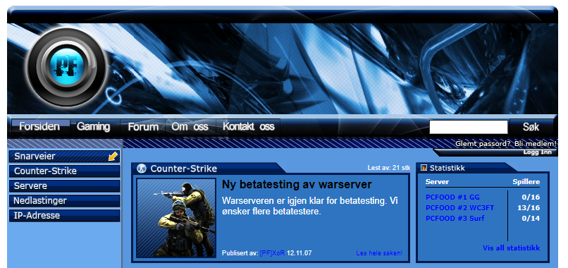
The golden age of pcfood.net was 2005-2010, where we ran a popular Counter-Strike 1.6 web server. We also had a cool, good-looking and interactive web page, with live statistics, and ability to rent a gaming server for free. We also had an active forum, and there were many users in our community. A snapshot of this webpage (courtesy of archive.org): https://web.archive.org/web/20071125212619/http://pcfood.net:80/
Around 2009, the CS server went down, and never came back online. The years after, the web pages have been kind of dead.
But now, I want to make pcfood.net great again! Now, as my personal blog, where I intend to write about topics I find interesting. To be continued….